

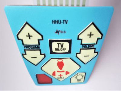
Only LEDs are integrated into this membrane keyboard, no switch functions. The print motif is printed with inkjet printing. The missing colour brilliance compared to silk screen print colours can be seen clearly.
Membrane keyboards, input devices
The membrane keyboard’s technology is simple, reliable, economical, variable and, most importantly, is attractive with regards to the graphic and functional design possibilities. The membrane keyboard overlay consists of at least two colour layers: one colour for detailed inscription and another for the background. In order to achieve better operation orientation and guidance, up to five layers of colour are used per membrane keyboard overlay. Spot colours are dominant, but halftone colours are also popular to be able to portray gradients with halftone printing.
Description
Possible circuit options
The printed circuit arrangement consists of two layers – an upper circuit and a lower circuit – which are separated by a film (spacer). The printed key creates contact with the lower circuit. Both circuits are connected to one another via their terminals on the terminal lug.
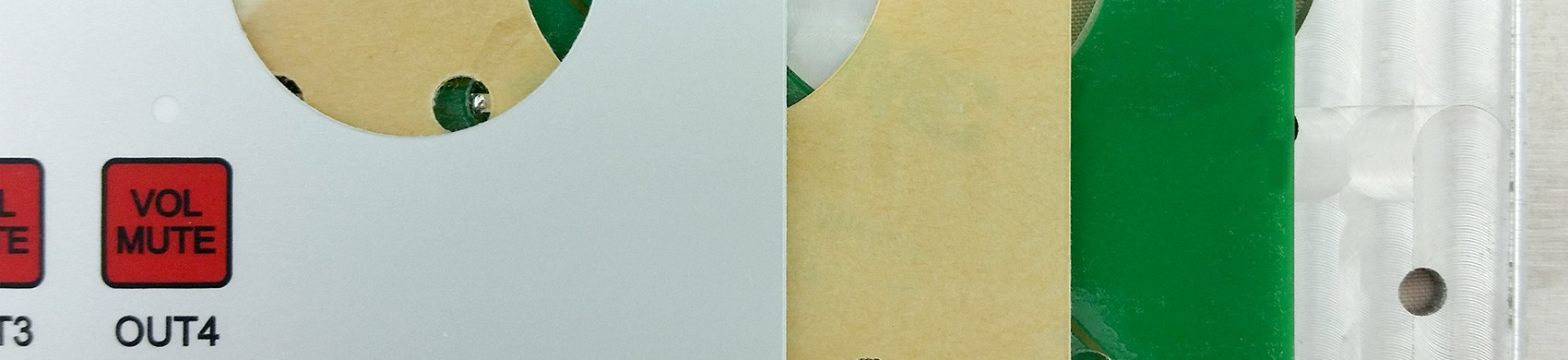
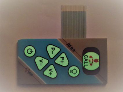
In contrast to printed circuit boards, conducting paths are printed with conductive paste on a polyester film. This allows for many options, but also restrictions with regards to the distance between keys and circuit layout, for example, the seven keys have one single, joint conducting path on one layer and seven other conductive paths for every single key on another layer. Thus, a total of eight conducting paths lead out from the conducting paths.
Wherever more keys are needed – for 12-key films, for example – an XY matrix configuration is preferred. In other words, one layer has three conducting paths for the column and the other layer has four conducting paths for the lines, which leads to a 3 x 4 matrix and a terminal lug with seven conductive paths. In this situation, the microprocessor interprets which key has been pressed and processes the resulting reply.
Terminal lug and connections
The membrane keyboard is connected with the processor through the terminal lug via the interface. The length of the terminal lug can be chosen individually and measures between 50 mm and 200 mm. There are various connection possibilities. Connectors with 2.54 mm grids are the most popular, which can be connected to a standard top bar on a circuit board.
Tactility in membrane keyboards
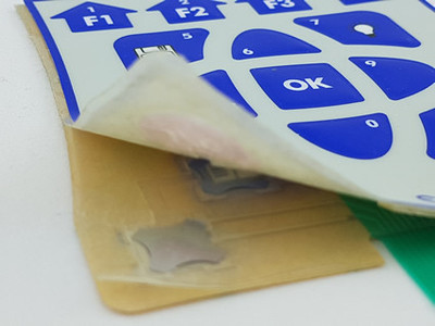
The standard structure of a membrane keyboard does not provide any tactile feedback, but rather an audio or visual display, which is enough for most users. Wherever physical feedback is necessary, tactile keys are an additional option to give the user feedback through their fingertips that the keystroke was successful. This is achieved with metal snap shields (snap domes, metal domes), which are integrated into the membrane keyboard and give off an acoustic click that can also be felt when pushing a key.
Haptics through arched keypads
The keys can be designed in such a way so that they cannot only be met visually, but also in terms of haptics with the fingertips, where the keypads are fitted with a dome through embossing or a cast resin coating.
EMI / RFI shielding
An additional layer – either fixed or with a grid pattern – can be built in between the graphic and the upper circuit. This layer makes it easier to cancel or derive the development of electrostatic charge on a person’s finger. Electrostatic discharge can disrupt or damage sensitive electrical components. An RFI shield, which is used on non-conductive composites, protects sensitive electrical appliances from electromagnetic high frequency disturbances.
Integrated SMD LEDs
Glued on LEDs can either be executed with their own circuit and terminal contact or integrated in the key circuit. To make sure the membrane keyboard doesn’t become to thick, the film is embossed over the LED, in which the LED then sits. The LED window in the film can either be transparent, coloured and translucent or almost invisible with the colour-disappearing effect.
Electroluminescence lights
Customers often desire backlighting, but in the past technology was expensive and the results disappointing. Toppress Siebdruck GmbH is currently testing new products and would like to accommodate your requirements and welcome your interest.
Electroluminescence systems are basically light capacitors. By applying an alternating voltage to the two electrodes – with one being translucent – the ZnS light crystals are stimulated to emit light. By building up conductive and isolating layers on a highly resistant plastic carrier, an individually designed illuminated area is produced. The EL films are mostly used as backlighting in speedometers or as full displays, for example, in lifts.